Product Description
Product Description
Product Parameters
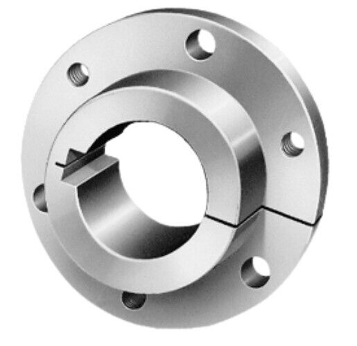
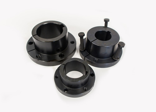
| product | Superior Precision Customized European Standard Taper Lock Bushing for Robotic Arm with ISO9001 |
| material | stainless steel , iron , aluminum ,bronze ,carbon steel ,brass etc . |
| size | ISO standard ,customer requirements |
| BORE | Finished bore, Pilot Bore, Special request |
| surface treatment | Carburizing and Quenching,Tempering ,Tooth suface high quenching Hardening,Tempering |
| Processing Method | Molding, Shaving, Hobbing, Drilling, Tapping, Reaming, Manual Chamfering, Grinding etc |
| Heat Treatment | Quenching & Tempering, Carburizing & Quenching, High-frequency Hardening, Carbonitriding…… |
| Package | Wooden Case/Container and pallet, or made-to-order |
| Certificate | ISO9001 ,SGS |
| Machining Process | Gear Hobbing, Gear Milling, Gear Shaping, Gear Broaching, Gear Shaving, Gear Grinding and Gear Lapping |
| Applications | Toy, Automotive, instrument, electrical equipment, household appliances, furniture, mechanical equipment,daily living equipment, electronic sports equipment, , sanitation machinery, market/ hotel equipment supplies, etc. |
| Testing Equipment | Rockwell hardness tester 500RA, Double mesh instrument HD-200B & 3102,Gear measurement center instrument CNC3906T and other High precision detection equipments |
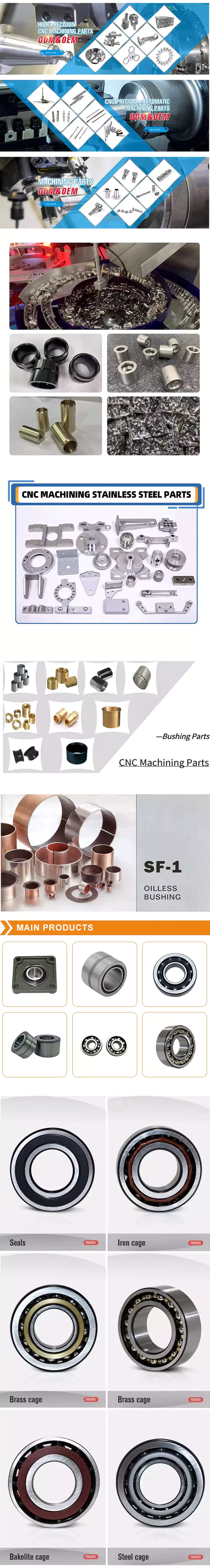
workshop & equipment
Production process
Certifications
Our Advantages
1 . Prioritized Quality
2 .Integrity-based Management
3 .Service Orientation
4 .150+ advanced equipment
5 .10000+ square meter factory area
6 .200+ outstanding employees
7 .90% employees have more than 10 year- working experience in our factory
8 .36 technical staff
9 .certificate ISO 9001 , SGS
10 . Customization support
11 .Excellent after-sales service
shipping
sample orders delivery time:
10-15 working days as usual
15-20 working days in busy season
large order leading time :
20-30 working days as usual
30-40 working days in busy season
FAQ
1. why should you buy products from us not from other suppliers?
We are a 32 year-experience manufacturer on making the gear, specializing in manufacturing varieties of gears, such as helical gear ,bevel gear ,spur gear and grinding gear, gear shaft, timing pulley, rack, , timing pulley and other transmission parts . There are 150+ advanced equipment ,200+ excellent employees ,and 36 technical staff . what’s more ,we have got ISO9001 and SGS certificate .
2: What are the common types of tooth profiles for synchronous belt pulleys?
A: The most common tooth profiles for synchronous belt pulleys are the trapezoidal (or T-type) and curvilinear (or HTD-type) profiles. The tooth profile determines the pitch diameter, which affects the overall ratio of the gear drive.
3 .How long is the delivery?
A: Small orders usually takes 10-15 working days,big order usually 20-35 days, depending on orders quantity and whether are standard size.
/* January 22, 2571 19:08:37 */!function(){function s(e,r){var a,o={};try{e&&e.split(“,”).forEach(function(e,t){e&&(a=e.match(/(.*?):(.*)$/))&&1
| Standard: | ANSI |
|---|---|
| Material: | Stainless Steel |
| Connection: | Welding |
| Samples: |
US$ 5/Piece
1 Piece(Min.Order) | Order Sample |
|---|
| Customization: |
Available
| Customized Request |
|---|
.shipping-cost-tm .tm-status-off{background: none;padding:0;color: #1470cc}
|
Shipping Cost:
Estimated freight per unit. |
about shipping cost and estimated delivery time. |
|---|
| Payment Method: |
|
|---|---|
|
Initial Payment Full Payment |
| Currency: | US$ |
|---|
| Return&refunds: | You can apply for a refund up to 30 days after receipt of the products. |
|---|
Can I find educational resources on the history and evolution of QD bushing technology?
If you are interested in learning about the history and evolution of QD (Quick Disconnect) bushing technology, there are educational resources available that can provide valuable insights. These resources can help you understand the development, advancements, and applications of QD bushings over time. Here are some avenues to explore:
- Manufacturer Websites: Some manufacturers of QD bushings provide educational resources on their websites. They may have sections dedicated to the history and evolution of their products, including QD bushings. These resources can include articles, whitepapers, or technical documentation that discuss the development of QD bushing technology and its various iterations. Visiting the websites of reputable manufacturers in the power transmission industry can provide you with valuable information.
- Industry Publications and Magazines: Trade publications and industry magazines often feature articles and case studies that delve into the historical aspects of industrial technologies. Publications such as Mechanical Engineering, Machine Design, or Power Transmission Engineering may cover topics related to QD bushing technology. Exploring their archives or conducting targeted searches can help you find informative articles on the subject.
- Engineering Books and Textbooks: Engineering books and textbooks on mechanical power transmission, machine design, or industrial components may contain chapters or sections dedicated to QD bushings. These resources can provide in-depth explanations of the technology’s history, design principles, and applications. Searching for relevant books in libraries, online bookstores, or academic databases can help you access comprehensive educational material.
- Technical Forums and Online Communities: Online technical forums and communities, such as engineering forums or mechanical engineering subreddits, can be valuable sources for discussions on the history and evolution of QD bushing technology. Engaging with professionals, engineers, and enthusiasts in these communities can provide you with insights, personal experiences, and references to further educational resources.
- Academic Research Papers: Academic research papers and journals in the fields of mechanical engineering, industrial engineering, or power transmission may contain studies or analyses related to QD bushing technology. Platforms like IEEE Xplore, Google Scholar, or academic databases provided by universities or research institutions can help you find scholarly articles that explore the historical aspects, design improvements, or performance evaluations of QD bushings.
When exploring these educational resources, it’s important to critically evaluate the information and cross-reference it with multiple sources. The history and evolution of QD bushing technology may vary depending on the specific manufacturer, region, or application. By gathering information from various reputable sources, you can develop a comprehensive understanding of the subject.
By utilizing these educational resources, you can gain knowledge about the history and evolution of QD bushing technology, enabling you to appreciate the advancements and applications of this important component in the field of mechanical power transmission.
Can I get advice on selecting the right QD bushings based on torque, speed, and load requirements?
When selecting the right QD (Quick Disconnect) bushings based on torque, speed, and load requirements, it is crucial to consider several factors to ensure optimal performance and compatibility. Here is some advice to guide you in the selection process:
- Torque Capacity: Determine the maximum torque that will be transmitted through the QD bushing in your application. This can be influenced by factors such as the power source, driven component, and operating conditions. Check the manufacturer’s specifications for the QD bushing’s torque capacity rating. It is important to choose a QD bushing that can handle the anticipated torque without exceeding its limits to ensure reliable and safe operation.
- Speed Limitations: Consider the rotational speed or RPM (revolutions per minute) at which the QD bushing will operate. Higher speeds can generate centrifugal forces, which can affect the performance and stability of the bushing. Verify the manufacturer’s specifications for the maximum recommended speed rating of the QD bushing. Ensure that the selected bushing can handle the anticipated speed without compromising its integrity or causing excessive wear.
- Load Requirements: Evaluate the applied load on the QD bushing, including axial, radial, and moment loads. Consider factors such as the weight of the driven component, dynamic forces, and any external forces acting on the system. Check the manufacturer’s specifications for the load capacity ratings of the QD bushing. It is essential to select a bushing that can withstand the anticipated loads without experiencing excessive deformation or failure.
- Material Selection: QD bushings are available in various materials, such as steel, stainless steel, and cast iron. Consider the environmental conditions, temperature range, and potential exposure to corrosive substances or contaminants in your application. Choose a QD bushing material that offers the necessary strength, corrosion resistance, and durability for the specific operating conditions.
- Consult with Manufacturers and Engineers: If you have specific and complex requirements or are unsure about the selection process, it is advisable to consult with QD bushing manufacturers or experienced engineers. They can provide expert guidance based on their knowledge and experience. Sharing comprehensive information about your application, including torque, speed, load requirements, and other relevant factors, will help them recommend the most suitable QD bushing for your needs.
It is crucial to note that selecting the right QD bushings goes beyond torque, speed, and load requirements. Other factors, such as shaft diameter, shaft fit, axial positioning requirements, and compatibility with the driven component, also play a significant role. Always refer to the manufacturer’s specifications, guidelines, and recommendations to ensure proper selection and installation of the QD bushings in your power transmission or conveying system.
By considering these factors and seeking professional advice when needed, you can make informed decisions and choose the right QD bushings that meet your torque, speed, and load requirements, leading to optimal performance and longevity of your system.
Can I get step-by-step instructions on installing QD bushings for different mechanical setups?
While I can provide a general overview of the installation process for QD bushings, it’s important to note that the specific installation steps can vary depending on the mechanical setup and the manufacturer’s guidelines. It is recommended to consult the manufacturer’s instructions and specifications for the specific QD bushing you are using. However, here is a general outline of the steps involved in installing QD bushings:
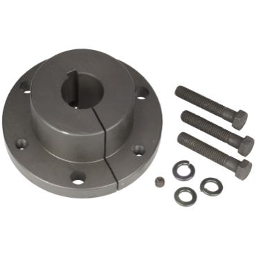
- Gather the necessary tools and equipment: Before you begin the installation process, ensure you have the required tools and equipment on hand. This may include wrenches, torque wrenches, a mallet or hammer, and any additional components or accessories specified by the manufacturer.
- Prepare the shaft and the mounting component: Clean the shaft and the inner bore of the mounting component to remove any dirt, debris, or old lubricants. Ensure that the shaft surface is smooth and free from any damage or burrs that could interfere with the installation process.
- Inspect the QD bushing: Before installing the QD bushing, inspect it for any visible damage or defects. Ensure that the tapered surfaces and the flange are clean and free from any debris that could affect the installation or the connection with the shaft and the mounting component.
- Position the QD bushing: Place the QD bushing over the shaft, ensuring that it aligns properly with the desired location on the shaft. The flange of the bushing should be facing the mounting component.
- Engage the QD bushing: Apply even pressure to the outer surface of the QD bushing to initiate the engagement. This can be done using a mallet or hammer. Ensure that the bushing is centered and properly seated on the shaft. Avoid applying excessive force that could damage the bushing or the shaft.
- Tighten the QD bushing: Using the specified torque value provided by the manufacturer, tighten the QD bushing by turning the tightening screws or bolts evenly. Follow the recommended tightening sequence provided by the manufacturer to ensure an even and secure connection. Be careful not to over-tighten the bushing, as this can cause damage.
- Verify the installation: After tightening the QD bushing, inspect the connection to ensure that it is secure and properly aligned. Check for any axial movement or play between the bushing, shaft, and mounting component. Verify that the mounted component is positioned correctly and securely fastened to the bushing.
- Complete the installation: Once you have verified the installation, proceed with any additional steps required for your specific mechanical setup. This may involve attaching other components, aligning belts or chains, or performing any necessary adjustments or calibrations.
It’s important to note that the above steps are a general guide and may not cover all possible scenarios or variations. Always refer to the manufacturer’s instructions and guidelines specific to the QD bushing you are using. Following the manufacturer’s recommendations will ensure proper installation and optimal performance of the QD bushing in your mechanical setup.
editor by CX 2024-05-03